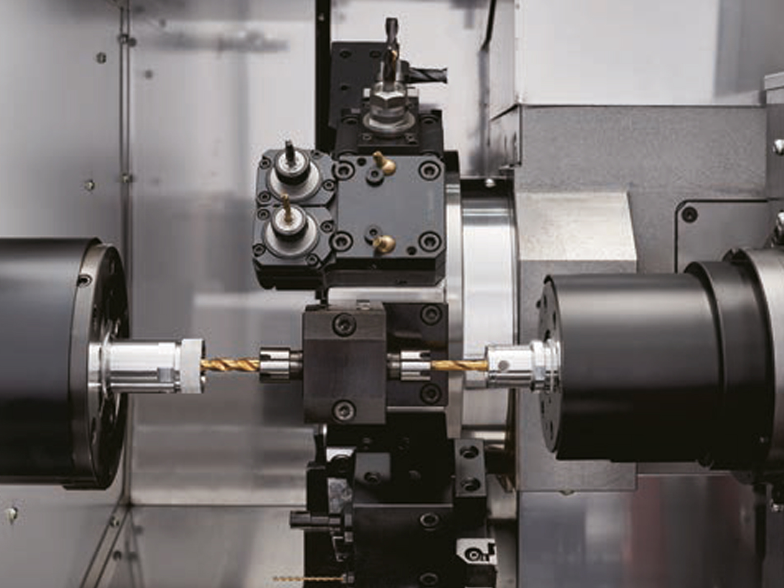
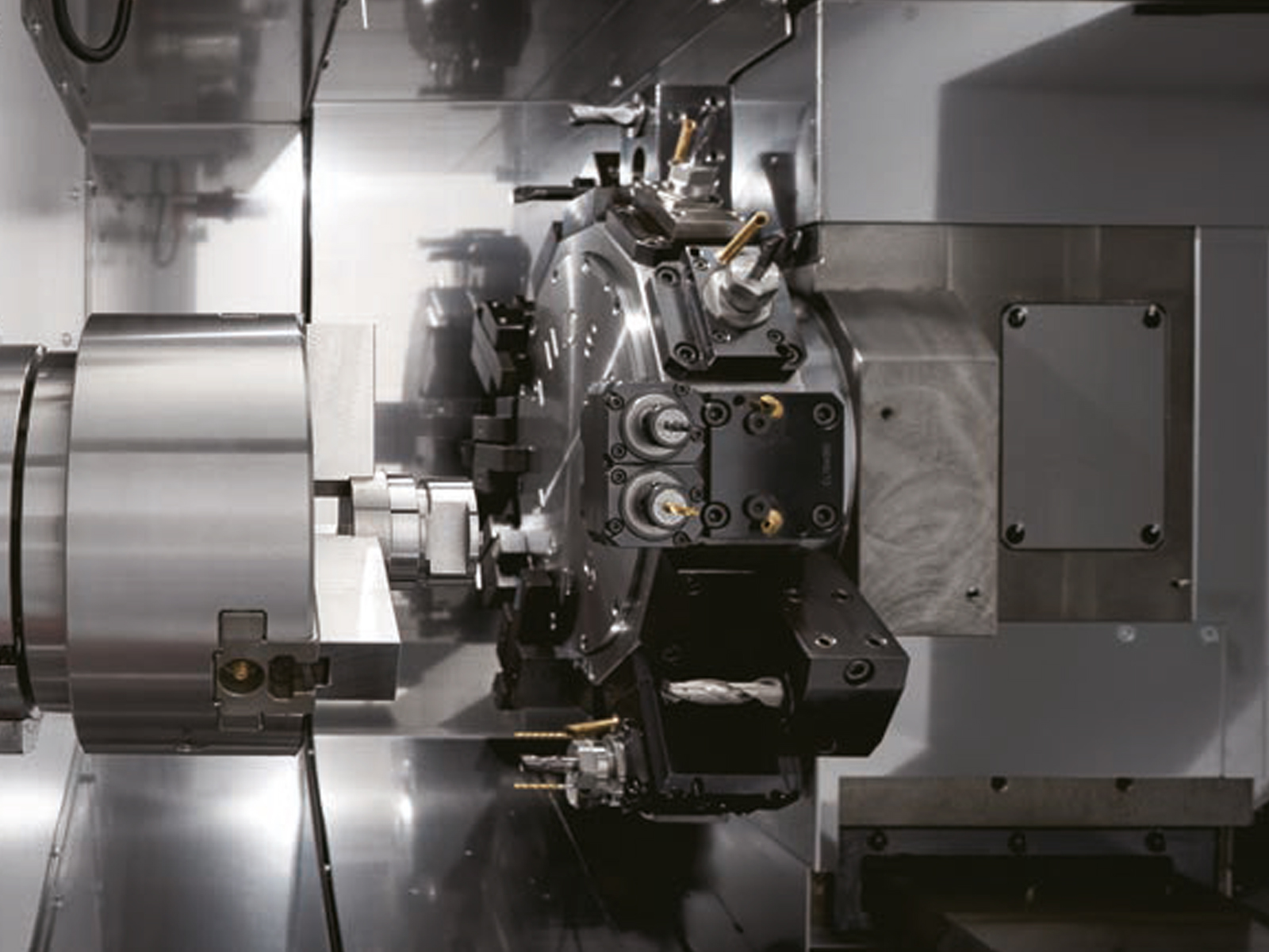
The BNA42SY CNC Fixed Head enhances the proven Miyano platform with increased rigidity, visibility, and advanced chip control.
A signature surface plate bed structure has been enlarged to improve vibration damping and cutting stability. Increased bed mass ensures smoother machining, even under heavy or interrupted cuts. A larger coolant tank helps maintain thermal stability for long production runs.
The turret features improved rigidity and now supports 12 tool stations with full Y-axis functionality. More tools and live positions enable complex machining in one setup with better productivity.
The latest models now include LFV technology as standard for improved chip control. LFV reduces swarf build-up, extends tool life, and improves chip evacuation in challenging materials.
The machine cover has been redesigned for better access, with a larger window and wider front opening.
Chip removal is easier, thanks to a larger chip port and better placement at the outer edge.
A standard dual-check safety system increases both machine safety and overall operator confidence.
The BNA42SY CNC Fixed Head is ideal for demanding jobs that require precision, control, and clean machining.

| Item | BNA-42CY5 | BNA-42SY5 | |
|---|---|---|---|
| Capacity (billet) | 135 mm | 135 / 110 mm | |
| Max. machining length | 200 mm (300 mm) | 100 mm (200 mm) | |
| Standard machining diameter | SP1 | 42 mm dia. | — |
| SP2 | — | 42 mm dia. | |
| Axes stroke | |||
| X axis | 140 mm | 140 mm | |
| Z axis | 285 mm | 285 mm | |
| Y axis | 70 (+/-35) mm | 70 (+/-35) mm | |
| B axis | — | 360 mm | |
| Number of spindles | 1 | 2 | |
| Spindle speed | SP1 | 60 to 6,000 min⁻¹ | 50 to 5,000 min⁻¹ |
| SP2 | — | — | |
| Closing tube through-hole diameter | SP1 | 43 mm dia. | — |
| SP2 | — | 30 mm dia. | |
| Collet chuck type | SP1 | Hardinge S20, DIN173E, B&S #22D, JPN34, Hainbuch |
JPN, DIN171E |
| SP2 | — | DIN173E, B&S #22 | |
| Power chuck type | SP1 | 5″ and 6″ hollow chucks | 5″ hollow chuck |
| SP2 | — | 4″ hollow chuck | |
| Number of tool posts | 1 | 1 | |
| Type of tool post | 12 ST. | 12 ST. | |
| Opposite side distance of tool post | 300 mm | 300 mm | |
| Max. turning radius of tool post | 505 mm dia. | 505 mm dia. | |
| Dimensions of tools used | ⧄ 20 mm | ⧄ 20 mm | |
| Dimensions of tool post holes | 25 mm dia. | 25 mm dia. | |
| Number of installed rotary tools | Max. 12 | Max. 12 | |
| Type of rotary tool drive | Independent clutch drive | Independent clutch drive | |
| Rotating speed of rotary tools | 50 to 5,000 min⁻¹ | 50 to 5,000 min⁻¹ | |
| Machining capacities | Drill | Max. 10 dia. | Max. 10 dia. |
| Tap | Max. M6 × 1 | Max. M8 × 1.25 (Limited to spiral and point taps for M8 × 1.25) Max. M8 × 1.25 for BSBM |
|
| Rapid feed rate | X axis | 20 m/min | 20 m/min |
| Z axis | 20 m/min | 20 m/min | |
| Y axis | 12 m/min | 12 m/min | |
| B axis | — | 20 m/min | |
| Slide thrust | X axis | 5 kN | 5 kN |
| Z axis | 5 kN | 5 kN | |
| Y axis | 6.7 kN | 6.7 kN | |
| B axis | — | 5 kN | |
| Tailstock travel distance | 200 mm | ||
| Morse taper size | MT2 | ||
| Max. slide thrust | 4.3 kN (at 3.4 MPa) | ||
| Min. slide thrust | 0.57 kN (at 0.45 MPa) | ||
| Drive method | Hydraulic | ||
| Spindle motor | SP1 | 11.7 / 5.5 / 5.5 kW (15% / 15 min / cont.) | 11.7 / 5.5 / 5.5 kW (15% / 15 min / cont.) |
| SP2 | 5.5 / 3.7 kW (15 min / cont.) | 5.5 / 3.7 kW (15 min / cont.) | |
| Rotary tools motor | 2.8 / 1.0 kW | 2.8 / 1.0 kW | |
| Coolant pump motor | 0.25 kW | 0.25 kW | |
| High-pressure coolant motor | 1.1 / 0.75 kW (60 / 50 Hz) | 1.1 / 0.75 kW (60 / 50 Hz) | |
| Power supply | AC 200 / 220 ±5% ~10%, 50 / 60 Hz ±1% | AC 200 / 220 ±5% ~10%, 50 / 60 Hz ±1% | |
| Power supply capacity | 16 kVA | 26 kVA | |
| Air pressure source | 0.5 MPa | 0.5 MPa | |
| Fuse capacity on facilities side | 75 A | 100 A | |
| Hydraulic tank capacity | 18 L | 18 L | |
| Lubricating oil tank capacity | 2 L | 2 L | |
| Coolant tank capacity | 225 L | 225 L | |
| Machine height | 1,745 mm | 1,745 mm | |
| Required floor surface area | W 2,260 × D 1,433 mm | W 2,350 × D 1,433 mm | |
| Machine weight | 3,430 kg | 3,880 kg | |