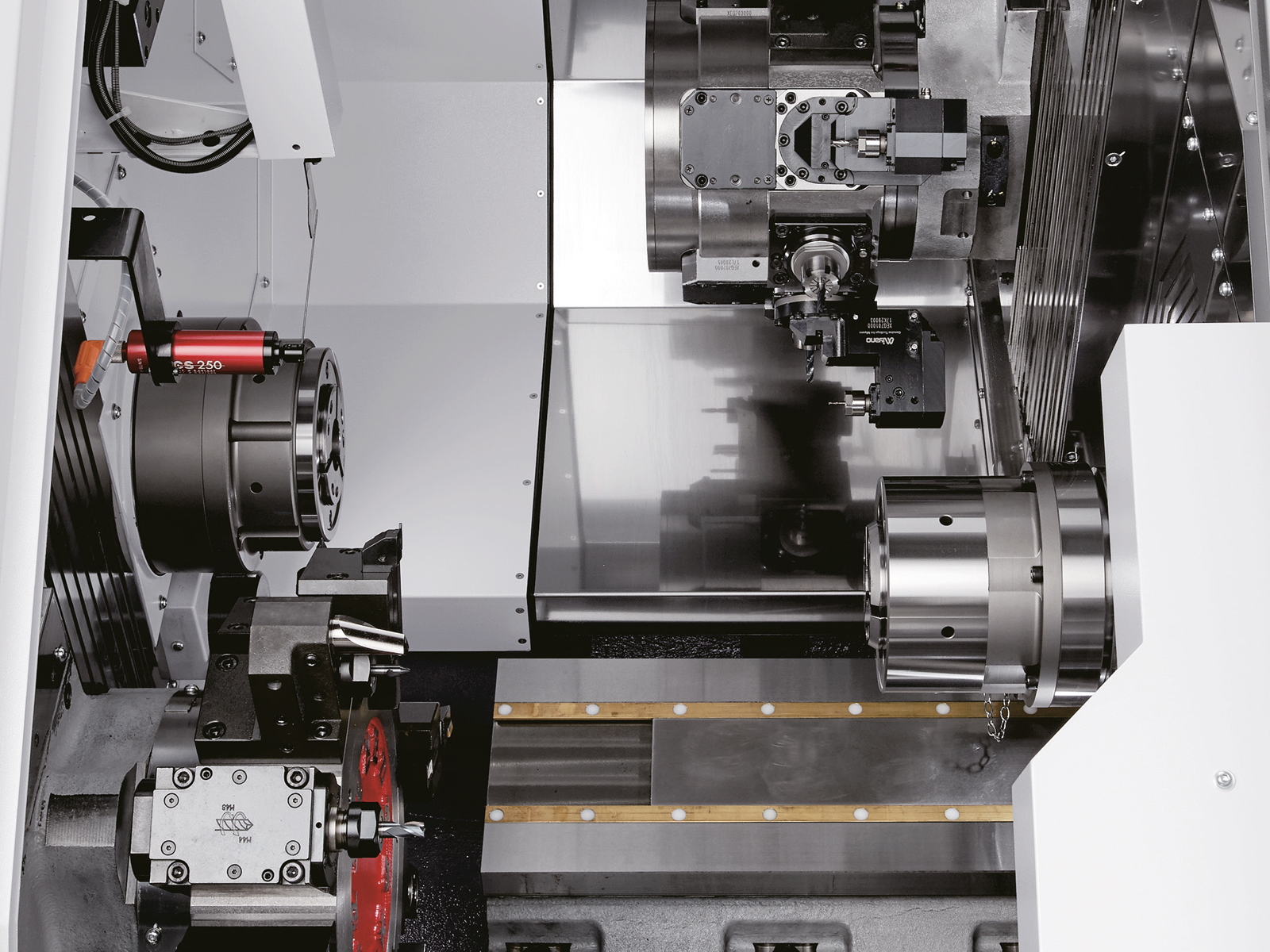
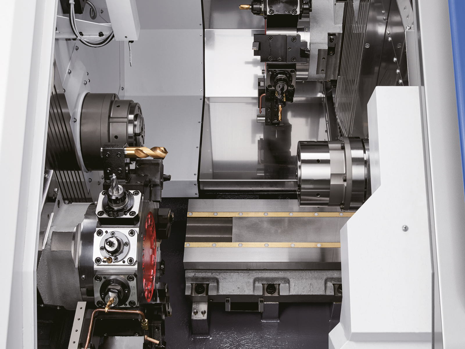
The BNE51/65MYY CNC Fixed Head is part of Citizen’s next-generation BNE series. It builds on the trusted precision and rigidity of earlier models. These new variants offer major upgrades in both machining flexibility and productivity.
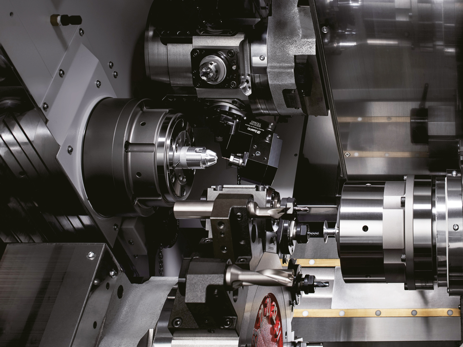
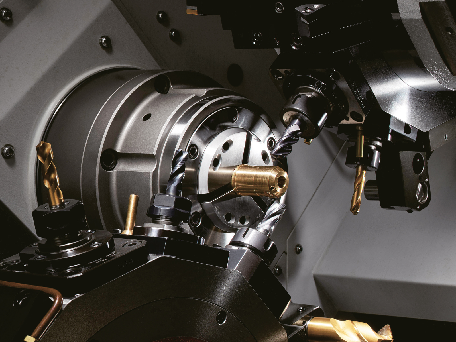
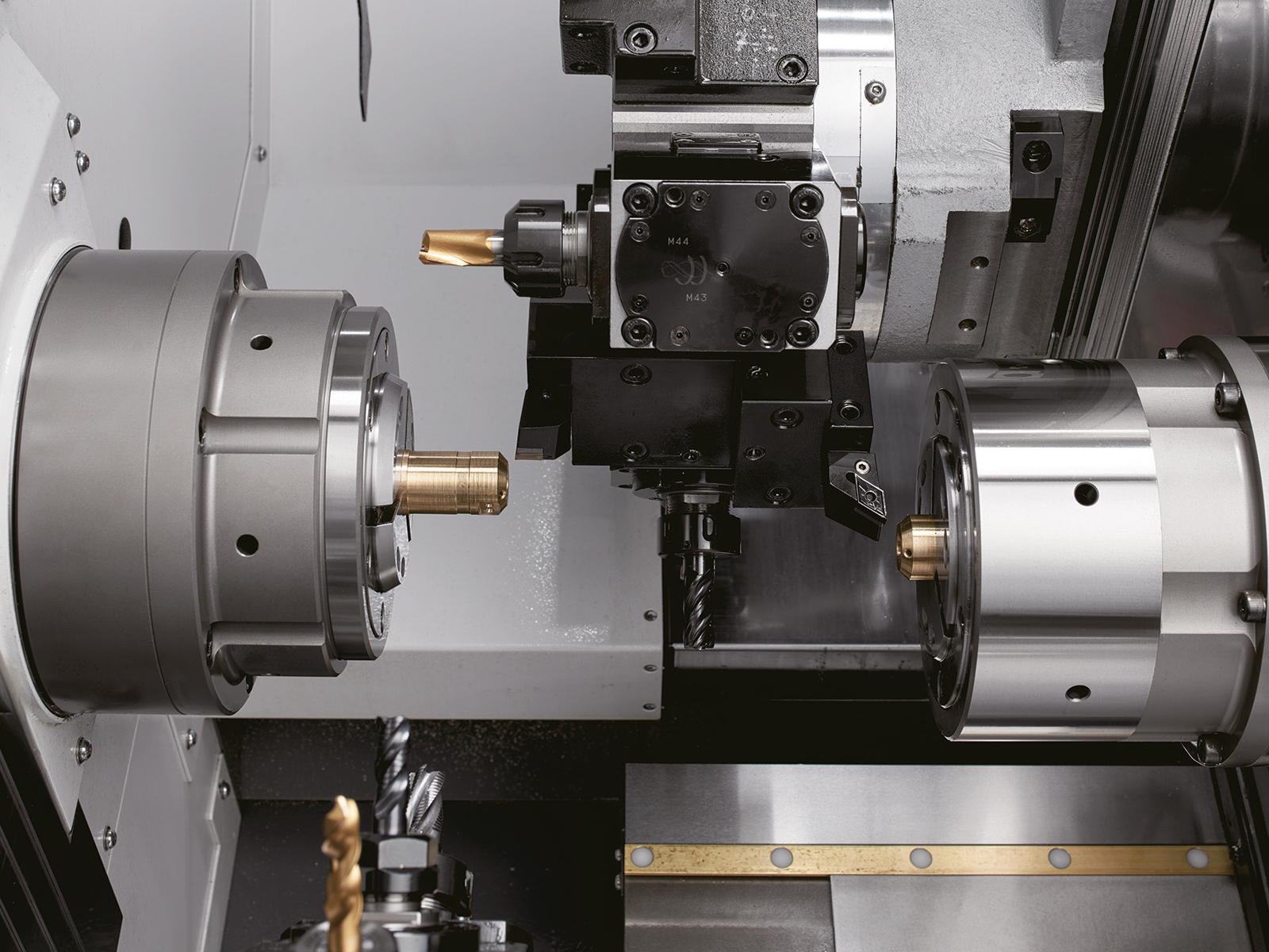
The MYY models feature twin Y-Axis, one on each turret. This allows for true simultaneous machining of complex parts. MSB versions add a programmable B axis to the upper turret for greater contouring capabilities. As a result, the BNE-51/65MYY supports superimposed machining and 3-tool simultaneous cutting with ease.
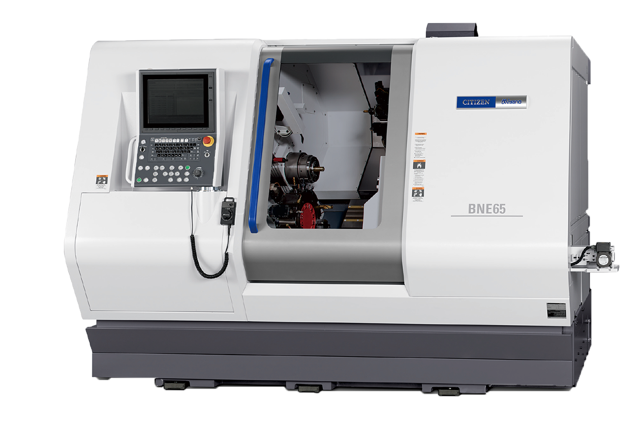
To support operator efficiency, Citizen redesigned the machine cover. It includes a large viewing window and improved access. The new HMI touchscreen control simplifies operation and reduces setup time. This interface also works seamlessly across Citizen’s Cincom and Miyano ranges.
Altogether, the BNE-51/65MYY delivers high-speed performance, advanced tooling options, and the flexibility needed for modern, high-precision production.
| Item | BNE-51MYY | BNE-51MSB | BNE-65MYY | BNE-65MSB | ||
|---|---|---|---|---|---|---|
| Machining capacity | ||||||
| Max. machining length | 195 mm | |||||
| Max. machining diameter | 51 mm dia. | 65 mm dia. | ||||
| Max. drilling diameter | SP1 | 25 mm dia. | ||||
| SP2 | 20 mm dia. | |||||
| Max. tapping diameter | SP1 | M22 × 2.5 | ||||
| SP2 | M20 × 2.0 | |||||
| Spindles | ||||||
| Number of spindles | 2 | |||||
| Main spindle speed | SP1 & SP2 | Max. 5,000 min-1 | ||||
| Main spindle collet chuck | SP1 | Hardinge S22 | Hardinge S26 | |||
| DIN 177E | DIN 185E | |||||
| HAINBUCH 51 | HAINBUCH 65 | |||||
| SP2 | Hardinge S22 | Hardinge S26 | ||||
| DIN 177E | DIN 185E | |||||
| HAINBUCH 51 | HAINBUCH 65 | |||||
| Power chuck type | SP1 & SP2 | 6″ 3-claw chuck, 6″ 2-claw chuck | ||||
| Travel distance | ||||||
| Slide travel distance | X axis | X1: 205 mm, X2: 205 mm, X3: 155 mm | ||||
| Z axis | Z1: 380 mm, Z2: 175 mm, Z3: 500 mm | |||||
| Y axis | Y1: +60/ – 40mm, Y2: ±40 mm | |||||
| Tool posts | ||||||
| Number of tool posts | 2 | |||||
| Type of tool post | HD1 | 12 ST. | 10 ST. | 12 ST. | 10 ST. | |
| HD2 | 12 ST. | |||||
| Dimensions of tools used | 20 mm | |||||
| Dimensions of tool post holes | 25 mm dia. | |||||
| Rotary tools | ||||||
| Number of installed rotary tools | HD1 | Max.12 | Max.10 | Max.12 | Max.10 | |
| HD2 | Max.12 | |||||
| Type of rotary tool drive | Independent clutch drive | |||||
| Rotating speed of rotary tools | 6,000 min-1 | |||||
| Machining capacities | Drill | 16 mm dia. | ||||
| Tap | M12 × 1.75 | |||||
| B axis (MSB only) | Drill | 10 mm dia. | ||||
| Tap | M6 × 1.0 | |||||
| Max. M8×1.25 for BSBM | ||||||
| Feed rate | ||||||
| Rapid feed rate | X1, Z1, X3, Z3 axes | 20 m/ min | ||||
| X2, Z2 axes | 18 m/ min | |||||
| Y1, Y2 axes | 12 m/ min | |||||
| Slide thrust | ||||||
| X1, Z1, X3 axes | 8.5 KN | |||||
| X2 axis | 11.3 KN | |||||
| Z2, Y1 axes | 6.6 KN | |||||
| Z3 axis | 5 KN | |||||
| Y2 axis | 5.8 KN | |||||
| Motors | ||||||
| Spindle motor | SP1 | 18.5/ 15 kW (30min./ cont.) | ||||
| SP2 | 11/ 7.5 kW (15min./ cont.) | |||||
| Rotary tools motor | SP1 & SP2 | 4.0 kW | ||||
| Required power source | ||||||
| Power supply | AC 200 ± 10% | |||||
| Power supply capacity | 47 KVA | |||||
| Air pressure source | 0.5 MPa | |||||
| Air pressure flowrate | 120 NL/min. (When using air blower for 1 sec. in 3 locations) | |||||
| Tank capacity | ||||||
| Hydraulic oil tank capacity | 18 L | |||||
| Lubricating oil tank capacity | 5 L | |||||
| Coolant tank capacity | 350 L | |||||
| Machine dimensions | ||||||
| Machine height | 2,070 mm | |||||
| Floor space | W 2,860 × D 2,190 mm | |||||
| Machine weight | 8,080 kg | 8,130 kg |