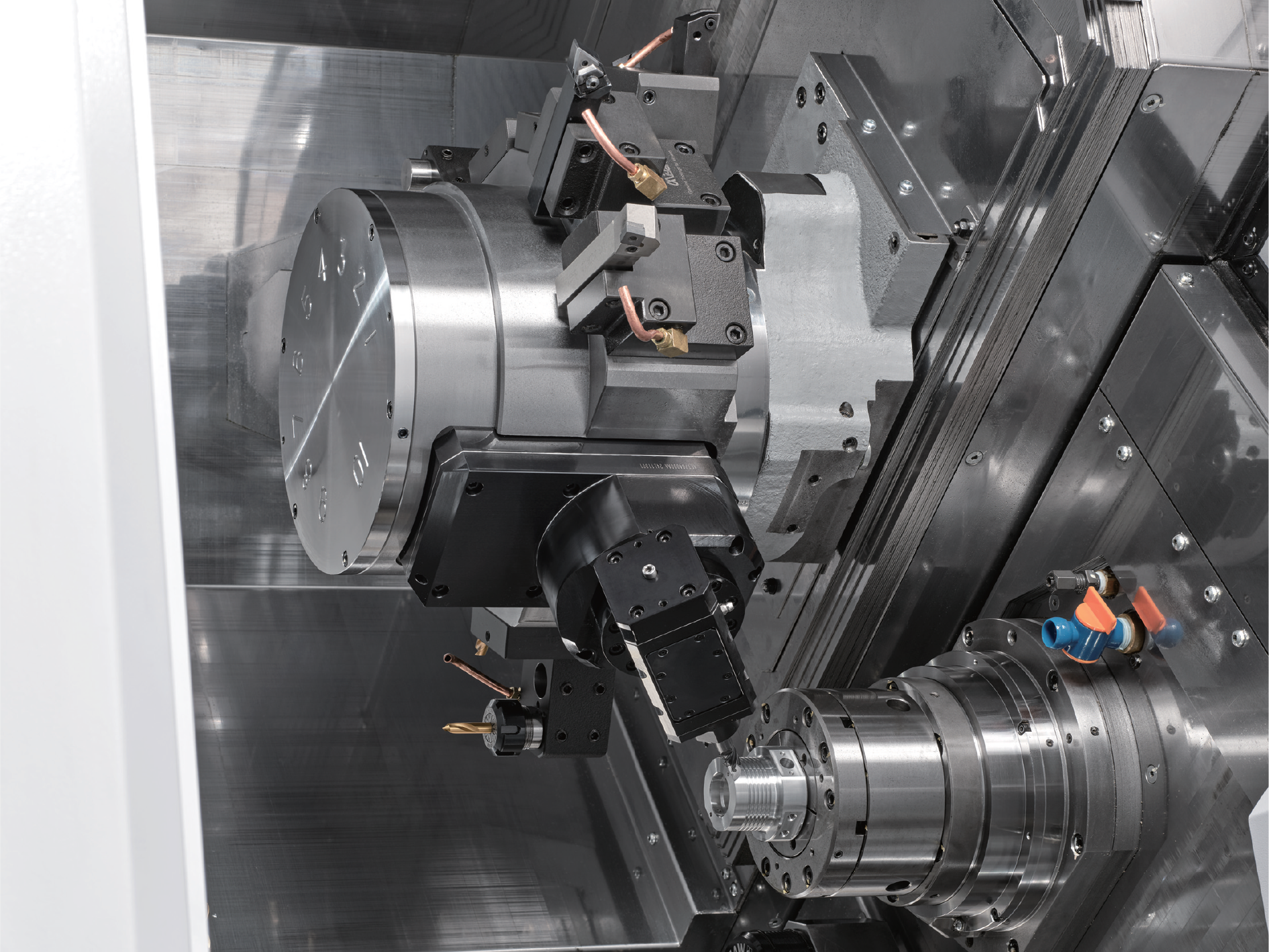
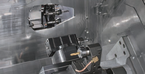
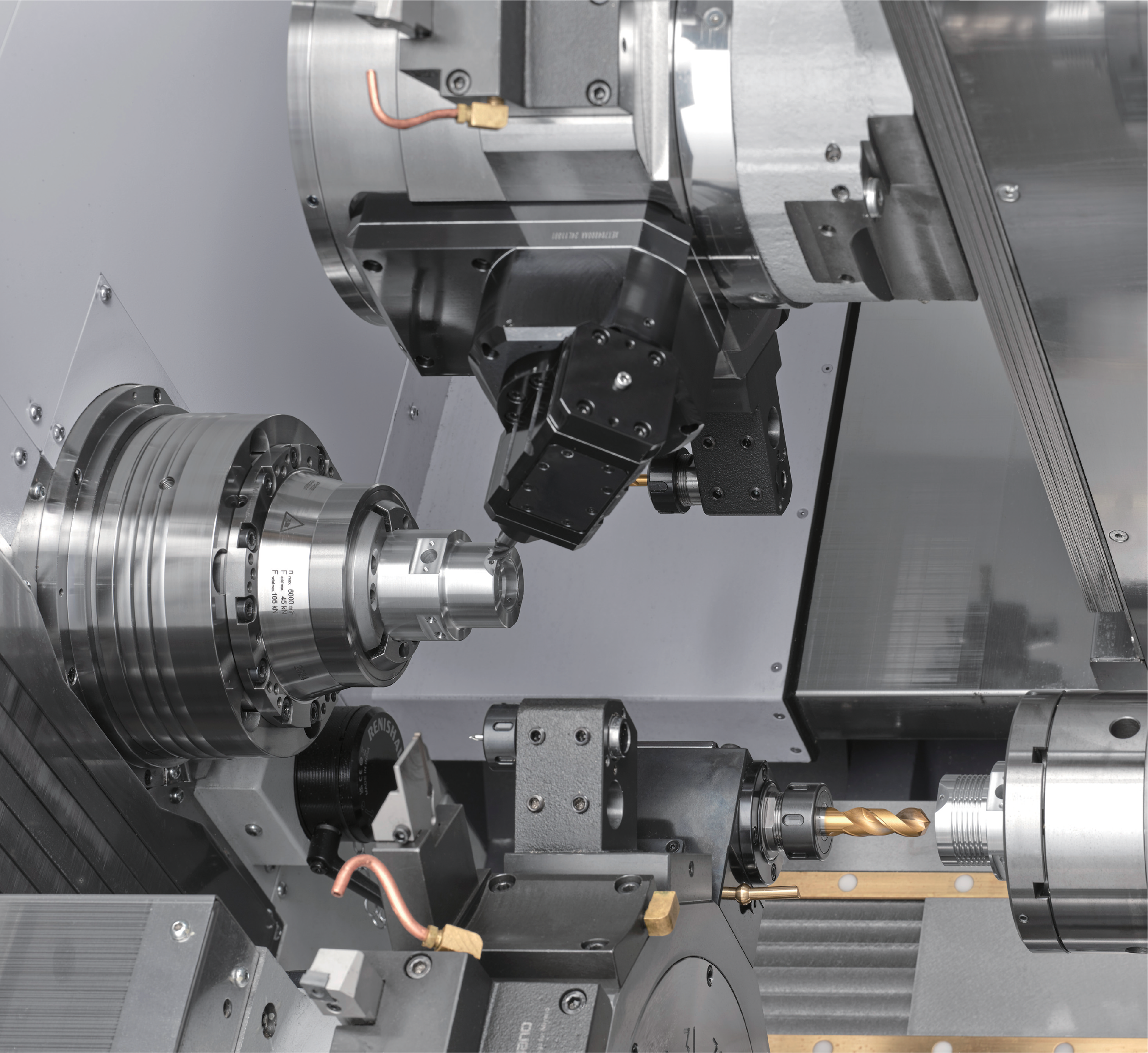
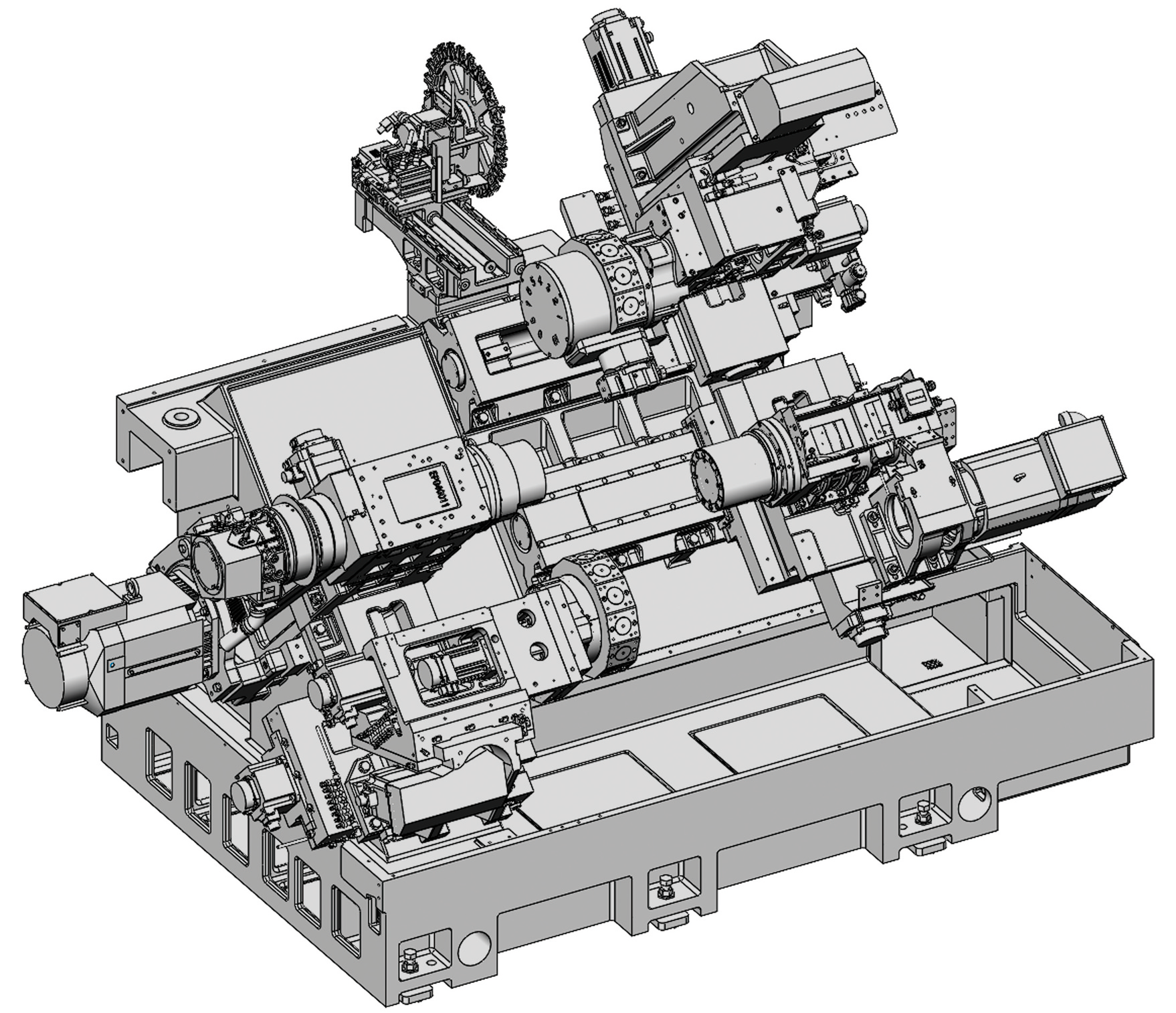
At the heart of the BNE-65ATC CNC Fixed Head is its twin Y-axis configuration, with one Y-axis assigned to each turret. This enables true simultaneous machining of complex components, allowing for superimposed operations and three-tool simultaneous cutting with exceptional stability and efficiency.
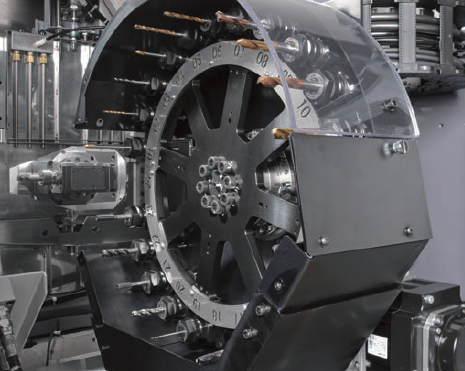
A key feature of the ATC model is the integrated 24-tool carousel, positioned at the rear of the machine. This system enables rapid tool changes for live tooling operations on the upper turret. This achieves an impressive chip-to-chip time of just 8.9 seconds. The ATC unit supports S20T-BT shank tooling, providing the flexibility to utilise a wide range of tools. This includes drills, end mills, and face mills.
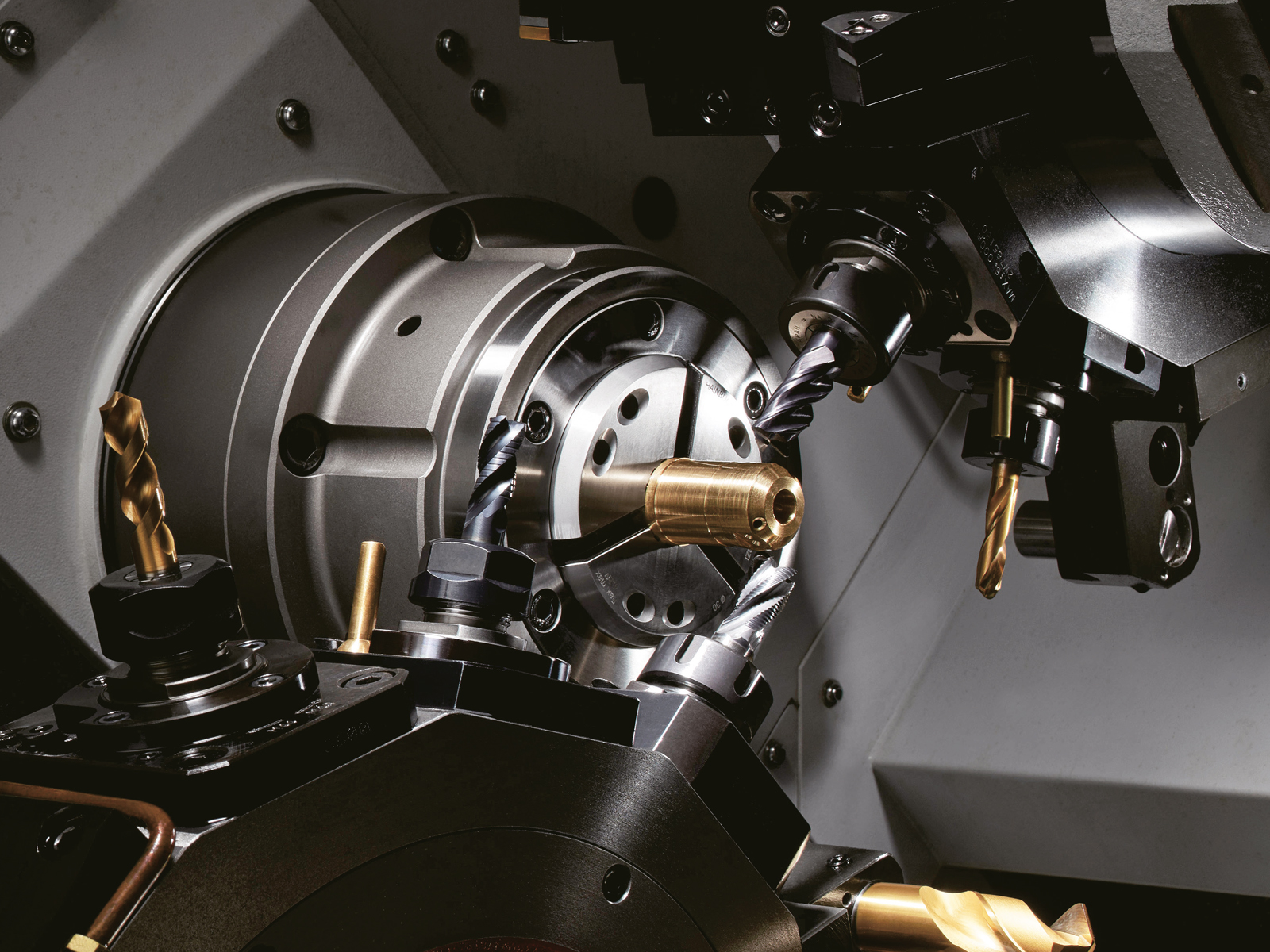
Enhancing this capability further, the upper turret is equipped with a tool spindle that can be indexed in the B-axis, enabling stable and rigid full 5-axis machining. This functionality allows drilling and tapping at any angle, significantly expanding machining versatility. When combined with the ATC system, the BNE-65ATC can efficiently handle a diverse range of complex workpiece geometries.
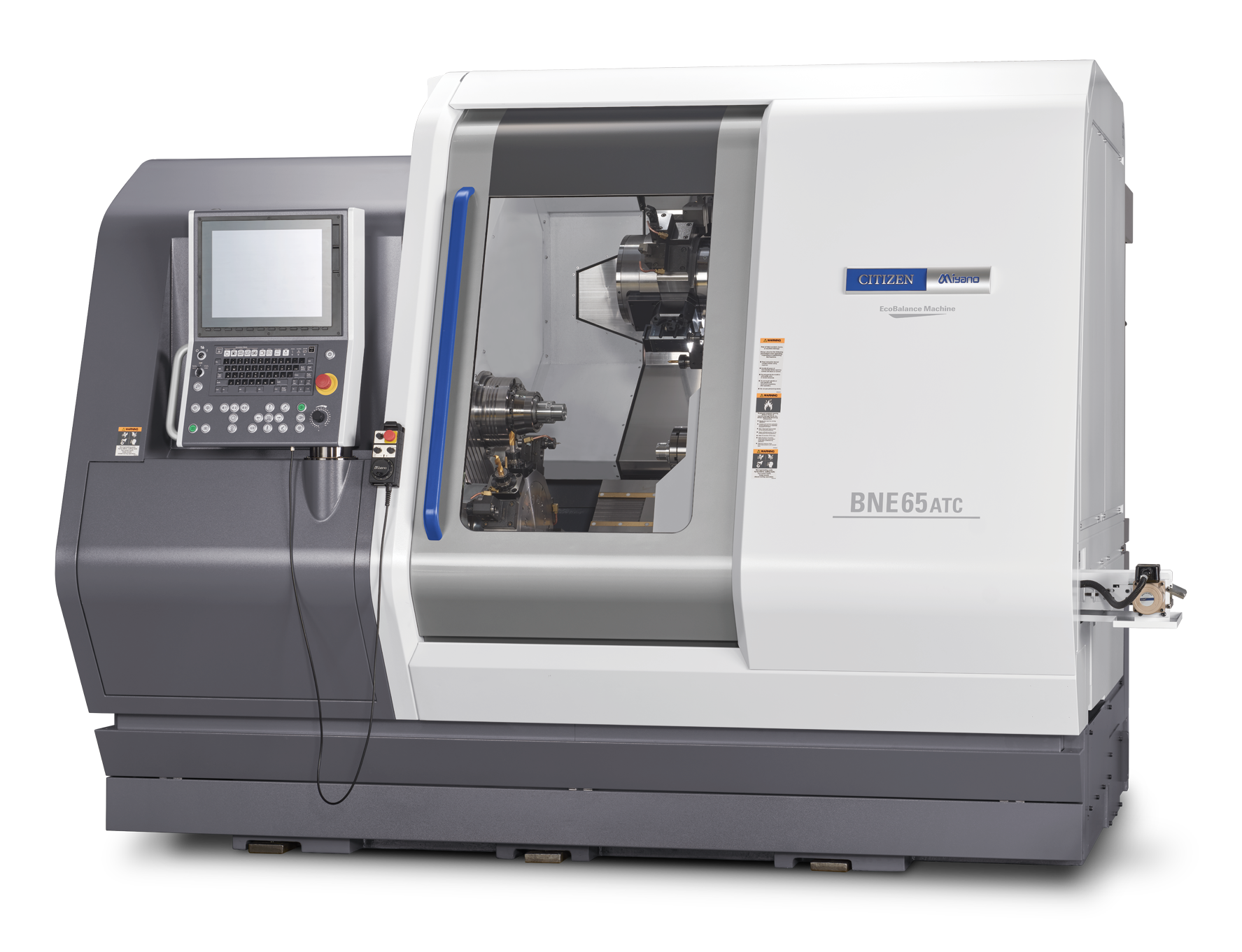
Bringing together high-speed performance, advanced tooling capability, and exceptional flexibility. The BNE-65ATC represents a major step forward in fixed head machining. It delivers the performance and adaptability required for today’s high-precision, high-efficiency manufacturing environments.
| Item | BNE-65ATC | |||||
|---|---|---|---|---|---|---|
| Machining capacity | ||||||
| Max. machining length | 195 mm | |||||
| Max. machining diameter | 51 mm dia. | |||||
| Max. drilling diameter | SP1 | 25 mm dia. | ||||
| SP2 | 20 mm dia. | |||||
| Max. tapping diameter | SP1 | M22 × 2.5 | ||||
| SP2 | M20 × 2.0 | |||||
| Spindles | ||||||
| Number of spindles | 2 | |||||
| Main spindle speed | SP1 & SP2 | Max. 5,000 min-1 | ||||
| Main spindle collet chuck | SP1 | Hardinge S26 | ||||
| DIN 185E | ||||||
| HAINBUCH 65 | ||||||
| SP2 | Hardinge S26 | |||||
| DIN 185E | ||||||
| HAINBUCH 65 | ||||||
| Power chuck type | SP1 & SP2 | 6″ 3-claw chuck, 6″ 2-claw chuck | ||||
| Travel distance | ||||||
| Slide travel distance | X axis | X1: 205 mm, X2: 205 mm, X3: 155 mm | ||||
| Z axis | Z1: 380 mm, Z2: 175 mm, Z3: 500 mm | |||||
| Y axis | Y1: +60/ – 40mm, Y2: ±40 mm | |||||
| Tool posts | ||||||
| Number of tool posts | 2 | |||||
| Type of tool post | HD1 | 9 ST. + 24ST. ATC | ||||
| HD2 | 12 ST. | |||||
| Dimensions of tools used | 20 mm | |||||
| Dimensions of tool post holes | 25 mm dia. | |||||
| Rotary tools | ||||||
| Number of installed rotary tools | HD1 | Max.12 | ||||
| HD2 | Max.12 | |||||
| Type of rotary tool drive | Independent clutch drive | |||||
| Rotating speed of rotary tools | 6,000 min-1 | |||||
| Machining capacities | Drill | 16 mm dia. | ||||
| Tap | M12 × 1.75 | |||||
| B axis (MSB only) | Drill | 10 mm dia. | ||||
| Tap | M6 × 1.0 | |||||
| Max. M8×1.25 for BSBM | ||||||
| Feed rate | ||||||
| Rapid feed rate | X1, Z1, X3, Z3 axes | 20 m/ min | ||||
| X2, Z2 axes | 18 m/ min | |||||
| Y1, Y2 axes | 12 m/ min | |||||
| Slide thrust | ||||||
| X1, Z1, X3 axes | 8.5 KN | |||||
| X2 axis | 11.3 KN | |||||
| Z2, Y1 axes | 6.6 KN | |||||
| Z3 axis | 5 KN | |||||
| Y2 axis | 5.8 KN | |||||
| Motors | ||||||
| Spindle motor | SP1 | 18.5/ 15 kW (30min./ cont.) | ||||
| SP2 | 11/ 7.5 kW (15min./ cont.) | |||||
| Rotary tools motor | SP1 & SP2 | 4.0 kW | ||||
| Required power source | ||||||
| Power supply | AC 200 ± 10% | |||||
| Power supply capacity | 47 KVA | |||||
| Air pressure source | 0.5 MPa | |||||
| Air pressure flowrate | 120 NL/min. (When using air blower for 1 sec. in 3 locations) | |||||
| Tank capacity | ||||||
| Hydraulic oil tank capacity | 18 L | |||||
| Lubricating oil tank capacity | 5 L | |||||
| Coolant tank capacity | 350 L | |||||
| Machine dimensions | ||||||
| Machine height | 2,070 mm | |||||
| Floor space | W 2,860 × D 2,190 mm | |||||
| Machine weight | 8,130 kg |